Embedded Networking and Communications
This assignment
aimed to design, build, and connect nodes with network to do some
specific functions in a synchronized way. While working in the
assignment I was trying to work in a flow of:
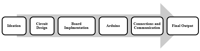
the very beginning of this assignment I was deciding over the idea
and applicability.
The idea is that the two communicators will be an
Arduino that will act as a master
that communicates with the board with my design as a slave
to follow some sort of instructions to get the final output
stimulated and the action is done. In each step of my workflow,
I was
learning some concepts and features through different online
resources, make a primary version, test, then implement the final
product.
Circuit Design
Self-Learning (EAGLE Software)
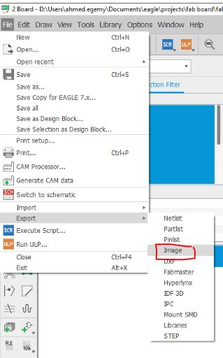
Firstly, I was learning some basics and advanced concepts in eagle to be able to design the needed circuit on it before implementation
Circuit
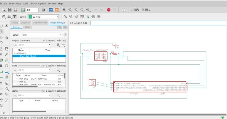
The steps taken to design the PCB with a purpose to COMMUNICATE:
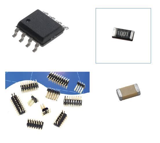
Put the components
ATTINY45
Pins Connectors
ceramic capacitor
1K Resistor
Connect as wire frames in the schematic view
Check overall connection and design
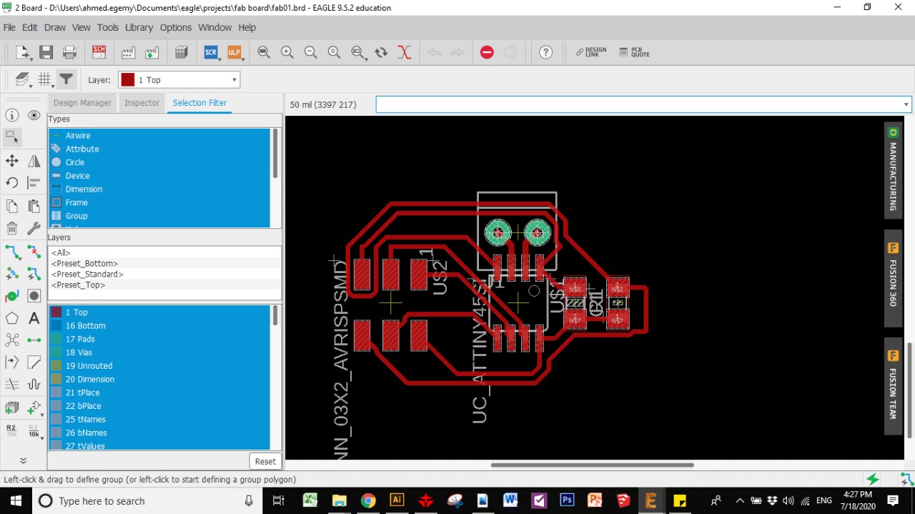
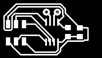
Go to board view to check the paths and PCB design
Adjust and develop the full board design with the traces and connecting nodes
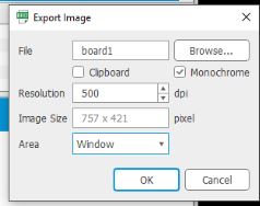
Eagle files
Board Implementation
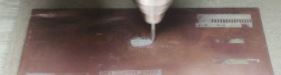
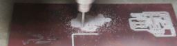
Milling
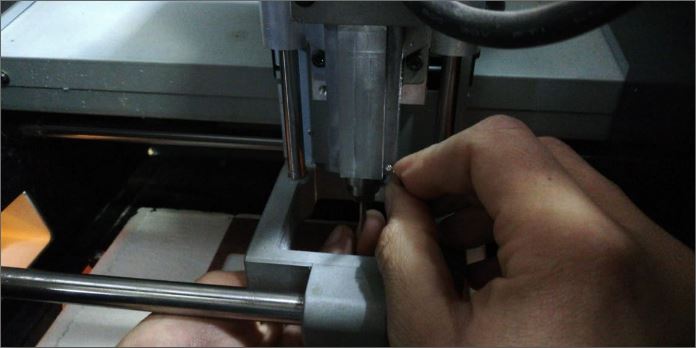
In the milling phase the PCB to be milled with the proper file extension. I used the machine available in the lab. I face some problems regarding the circuit finish and I overcame them all in the second trial.
Then Let's go for implementation
I've used SRM20 CNC milling machine and you can see all the deatils of machine and process from my electronics production assignemnt
RML machining file
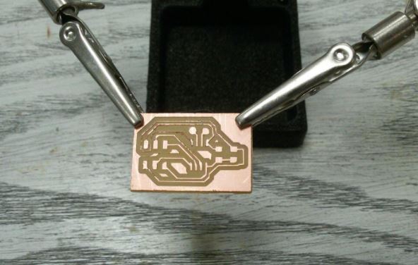
Soldering
After finishing PCB milling, the board is ready to be assembled with the components based on the provided design above.
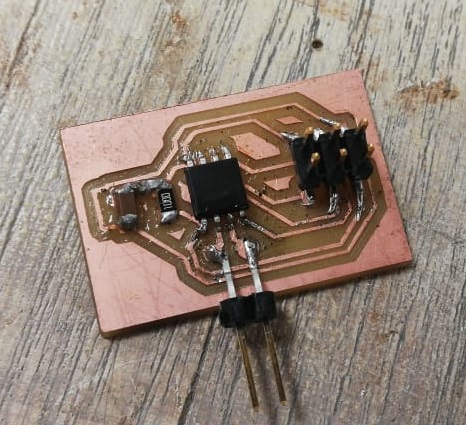
After implementing and soldering:
Important note: Make sure from the soldering as much as you can, Beacuse while connecting ther'es a lot of trials and a lot of plug-in plug-out specially with connectors, So this can pull the connectors out of the soldering and can affect the fixture of components which will affect the communication.
Arduino
Self-Learning:
This was a fruitful tutorial about the Arduino process of what I want to do in the assignment from burning the codes on the board and the Arduino and how the programs will let these two hardware products communicate in an efficient way
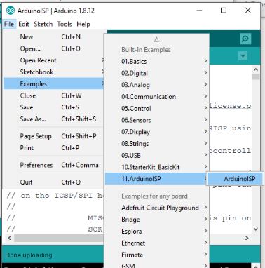
Prepare Arduino
In this step I was preparing the Arduino to be programmed by uploading Arduino ISP over it.
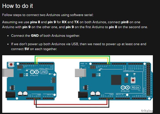
Connections and Communication (Network)
This is the phase of getting the final product ready to be used in a flow of steps as follows:
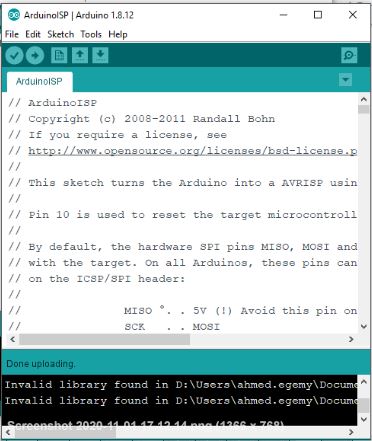
Uploaded Arduino ISP code on the Arduino board to make it a programmer.
Burn the program of communication that will be used in my own board on another Arduino to test the functionality and validity of the code. In this step the two Arduino boards have communicated wirily that made me sure that the code is functioning well before burning it on my communication board
// Include the Software Serial library
#include  // Define a Software Serial object and the used pins
SoftwareSerial softSerial(8, 9);
// LED Pin
int LED = 13;
void setup()  {
    softSerial.begin(9600);
    pinMode(LED, OUTPUT);
}
void loop()  { // Check if there is anything in the soft Serial Buffer
    if (softSerial.available())  {
    // Read one value from the soft serial buffer and store it in the variable com
    int com = softSerial.read();
    // Act according to the value received
    if (com == 'x')  {
    // Stop the LED
    digitalWrite(LED, LOW);
    }     else if (com == 'a')  {
          // Start the LED
          digitalWrite(LED, HIGH);
            }
       }
    }
Slave code, In case of the board change (8,9) to (3,4) and LED= 13 to LED = 0 or 1 (based on which pen you want to make it positive)
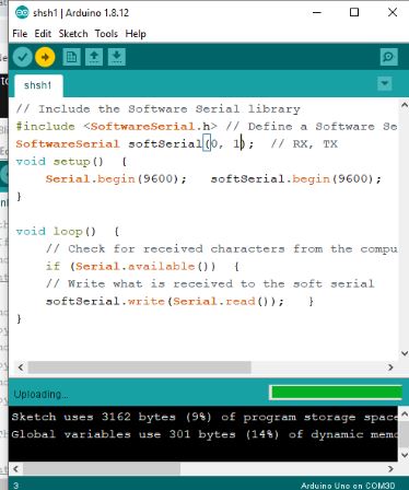
// Include the Software Serial library
#include  // Define a Software Serial object and the used pins
SoftwareSerial softSerial(8, 9);  // RX, TX
void setup()  {
    Serial.begin(9600);   softSerial.begin(9600);
}

void loop()  {
    // Check for received characters from the computer
    if (Serial.available())  {
    // Write what is received to the soft serial
    softSerial.write(Serial.read());   }
}
Master code to burn on the arduino that connected to the computer
Arduino-Arduino communication
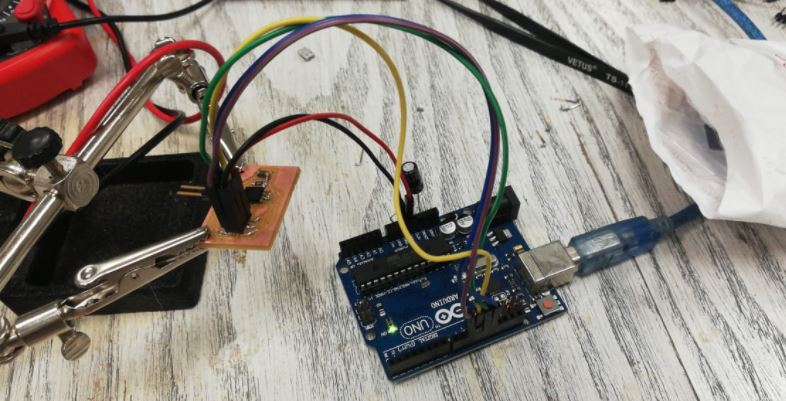
Disconnect the testing Arduino and replaced it with my board
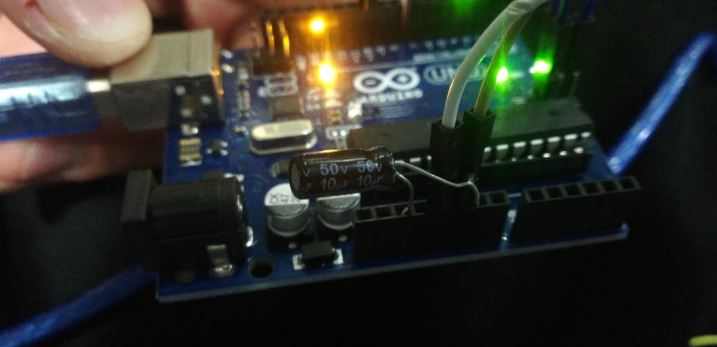
Connect 10uf capacitor to reset and GND to prevent the arduino from resetting after burnining the code(find the full details in the tutorial above)
Prepare my own board by burn on it the bootloader to be ready for programming
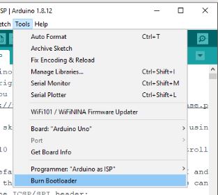
Importatnt:Make this step when you open a new and empty window of Arduino
Burn the communication tested program that will allow the board to be the slave that follows the master Arduino and allows the board to light or off when it receives the signal from serial monitor from the Arduino to do so, Then connect VCC,GND,TX and RX ...
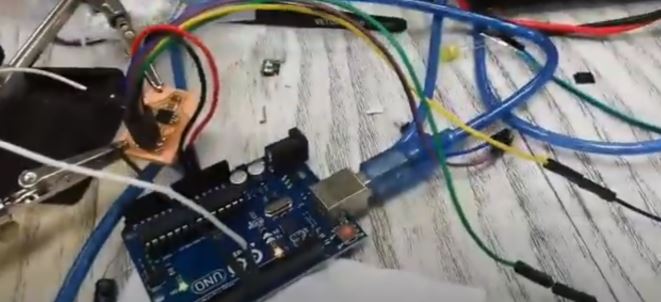
The final output is now ready for the use: Arduino and another board -made on my own- are communicating to light or switch off based on an Arduino signal to do so
Arduino source file
Done
- Design a board.
- Implement a board on CNC milling.
- Connections.
New Learned
- Soldering better.
- How to program boards by boards.
- How to make a communication.
Enjoyed with
- Trials.
- Debugging
- Learning advanced soldering skills.